applYING UML FOR RELATIONAL DATA MODELING
1. Introduction
Before
Unified Modeling Language (UML) was standardized in 1997, multiple modeling
notations were used for object-oriented modeling, which limited the spread and
advancement of modeling techniques and tools. UML was quickly adopted by
software engineers and academia and has become a de facto standard for modeling
architectures of software systems. Numerous UML tools have been developed and
are currently available in the market. Although UML was primary dedicated to
object-oriented modeling, it was also made extendable by introducing UML
profiles, which define additional semantics that can be applied to standard UML
elements in order to cover specifics of particular technologies and domains.
This was extremely useful because the wide spread of UML and tools supporting
UML notation made it the most used and understood modeling language, which
could be reused for multiple purposes. Multiple UML profiles were standardized
by OMG consortium, such as UML Profile for Schedulability, Performance and
Time, UML Profile for Enterprise Distributed Object Computing (EDOC), and
others available at http://www.omg.org.
Additionally, multiple vendor-specific UML profiles were introduced and
supported in various UML tools. In 2001, OMG launched Model Driven Architecture
(MDA) initiative (OMG, 2003a), which introduced an idea of model-driven
development that requires modeling at different abstraction levels. UML
profiles is the key technology for supporting this. Data modeling is one of the
most important issues in software engineering. Relational database management
systems (RDBMS) have been a state-of-the-art method for data persistence for
several decades. Although object-oriented database management systems (OODBMS)
is a promising new approach, so far it is less applied than RDBMS because of
lack of standards, immature technology, performance, scalability and other
issues. Therefore relational data modeling is very important for implementing
modern software systems. Entity Relationship Diagrams (ERD) have been widely
used for modeling relational databases. However, extending UML by introducing
profile for modeling relational data can replace ERD, which is a very tempting
approach since developers then could reuse their UML tools for database
modeling. Additionally, this enables possibility of other benefits related to
code engineering functions provided in state of the art UML tools. Developers may
benefit from using UML model to generate Data Definition Language (DDL)
scripts, which can be executed on database systems to create specified tables.
It may also be helpful to reverse DDL script into UML model. Retrieving UML
models from existing databases is useful for maintaining deployed systems.
Unfortunately, there is no standardized UML profile for relational data
modeling so far. In this paper we will shortly review the approaches of
supporting relational data modeling in UML and give a detailed description of
our approach to this problem, which was implemented in one of the leading UML
tools – MagicDraw UML, available at http://www.magicdraw.com.
2. Review of Existing
Approaches
Since
object-oriented modeling became a mainstream paradigm and database is an
essential part of almost any larger information system, the approach to reuse
object-oriented UML notation for modeling database structures seemed very
attractive. Rational Software, which was later acquired by IBM, published a
couple of papers on modeling entity relationships, see (IBM, 2003), and on
mapping objects to data models, see (IBM, 2003a). They also proposed UML
profile for data modeling in (Naiburg, 2001) and supported it in their UML tool
Rational Rose. Multiple books were published on the subject of using UML for
database modeling including (Muller, 1999), (Naiburg, 2001) and (Ambler, 2003).
UML capabilities for modeling data were compared to other modeling notations
like Object Role Modeling (ORM) (Halphin, 1999). Scott Ambler, one of the
pioneers of the agile development methods, maintains a site http://www.agiledata.org, in which
multiple agile methods for developing data-based solutions are presented
including suggested strategies for mapping objects to relational data
structures (Ambler, 2004) and their version of UML profile for database
modeling (Ambler, 2004a). In multiple UML modeling tools, such as Oracle
JDeveloper, Sybase PowerDesigner, Rational Rose, Borland TogetherJ, ERWin and
others, some functionality for modeling database structures is supported.
However, support for multiple database vendors and DDL engineering functions is
usually very limited. The MDA movement manifests transforming platform-independent
models into platform-specific models, which could be applied for turning
conceptual models into database models and adding technology-specific details.
This is usually implemented by plugging in technology-specific UML profiles and
modules describing rules for transformation (OMG, 2003a). However, currently
most MDA tools are still immature. We will present UML profile for database
modeling supported in MagicDraw UML and solutions for generating and reversing
of DDL script and retrieving data structures from deployed databases. We will
also present a case study demonstrating how conceptual UML model is transformed
into database-specific UML model. Such a transformation can be effectively
automated in mature MDA tools, which we believe is the near future.
3. Database Modeling with
MagicDraw UML
MagicDraw
UML provides UML profile for DDL containing stereotypes and tagged definitions
used to add database-specific semantics to UML elements. It also includes data
types for all major database systems supported in MagicDraw UML. Using this
profile, you can create DDL diagrams based on classes enhanced with the profile
stereotypes. DDL script can be generated from UML model specified in DDL
diagrams. DDL-specific UML model can also be reversed from DDL scripts and
databases.
3.1. UML Profile for DDL:
Mapping Relational Database Concepts to UML Elements
The mapping of most database concepts to UML
elements is pretty intuitive. Existing UML profiles suggest basically the same
mappings except for constraints. We present MagicDraw UML mappings for in Table
1 and constraint mappings in Table 2.
Table 1 – Relational database concept
mappings to UML elements
|
DB
Concept |
UML
Element |
Stereotype |
Additional
Description |
|
Database |
Package |
<<database>> |
Stereotype icon is
provided |
|
Schema |
Package |
<<schema>> |
Stereotype icon is
provided |
|
Table |
Class |
<<table>> |
Stereotype icon is
provided; contains tagged value for specifying table type |
|
View |
Class |
<<view>> |
Stereotype icon is
provided |
|
Column |
Attribute |
|
Attribute types have
to correspond to data types supported in target database |
|
Constraint |
BehavioralFeature |
Constraint-specific
stereotypes |
Various database
constraints are mapped to specific stereotypes on class attributes or are
presented as operations |
|
Trigger |
BehavioralFeature |
<<trigger>> |
Presented as
operation and contains tagged values for defining trigger action parameters |
|
Index |
BehavioralFeature |
<<index>> |
Presented as
operation with argument of indexed field |
Table 2 – Mapping relational
database constraints to stereotypes on attributes and operations
|
Constraint |
Stereotype |
UML
Element |
Additional
Description
|
|
Primary key |
<<PK>> |
Attribute,
BehavioralFeature |
Primary key
stereotype is usually applied on a single attribute or is represented as an
operation |
|
Foreign key |
<<FK>> |
BehavioralFeature |
Foreign key is
represented as a directed association with named ends and operations |
|
Uniqueness |
<<unique>> |
Attribute,
BehavioralFeature |
Unique stereotype is
usually applied on a single attribute or is represented as an operation |
|
Null |
|
|
Represented as
attribute multiplicity 0..1 |
|
Not null |
|
|
Represented as
attribute multiplicity 1 |
|
Check |
<<check>> |
BehavioralFeature |
Represented as an
operation with argument of constrained field and contains tagged value for
defining check condition |
|
Identifying |
<<identifying>> |
Association |
Applies on foreign
key associations if the relationship is one-to-one |
|
Non identifying |
<<non-identifying>> |
Association |
Applies on foreign
key associations if the relationship is one-to-many or by default |
3.2. Generating and
Reversing DDL Scripts
Generating and reversing DDL scripts is
implemented as usual MagicDraw UML code engineering function similar to Java,
C++, C# source code or XML Schema generation or retrieval. The usual activity
flows for generating and reversing DDL scripts are given in UML activity
diagram in Figure 1 bellow.
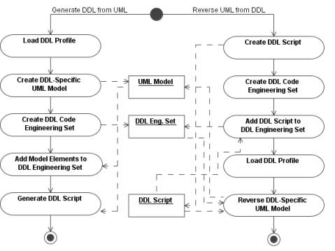
Figure 1 – Activity flows for
generating DDL script from UML model and reversing UML model from DDL script
3.3. Retrieving UML Model
for Relational Data Structure from Existing Databases
UML model can be retrieved from existing
database, which is a powerful tool for analyzing already deployed systems. The
retrieval of database structure is implemented via connecting to database using
JDBC, which provides access to database-specific implementation of interface DatabaseMetaData
contains methods for getting meta data about database structure, see (Sun,
2003). This theoretically allows to reuse code for retrieving data structure
from any database providing JDBC driver. However, in practice, many drivers do
not implement particular methods and in such a case some information about data
structures cannot be retrieved. However, the principle of retrieving database
structure is the same for any database type – user has to provide database
connection URL, JDBC driver files and driver class name, username and password,
catalog and schema that should be retrieved. Additionally, user may choose
whether to retrieve foreign keys and specify driver-specific properties, which
are realized as name-value pairs. The MagicDraw dialog for specifying this is
shown in Figure 2.
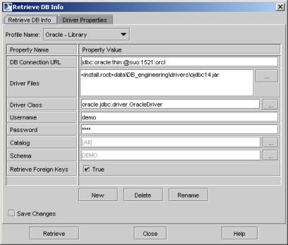
Figure 2 – Dialog for retrieving
database structure
After
user specified all the necessary properties, the database structure is
retrieved as UML model with stereotypes and tagged definitions from DDL
profile. The user can also automatically create class diagrams for retrieved
UML model elements.
3.4. Supporting Different
Database Dialects
Multiple
relational database management systems (RDBMS) are available from various
vendors. Oracle, Sybase, MS SQL Server, Informix and DB2 are the most popular
full-featured heavyweight database systems. For smaller applications
lightweight RDBMS products like MySQL, PointBase, or MS Access are used. There
has been a lot of work for standardizing query languages for relational
databases in order to make development of systems independent from database
vendor. Unfortunately, it was only partially successful. Most vendors claim
that they are compliant with recent SQL standard. This is usually correct for
most common SELECT, INSERT, DELETE and UPDATE queries, but DDL query
implementation is extremely different from vendor to vendor. Not all vendors
support features like database catalogs and schemas. Therefore it is necessary
to provide editable properties for generating DDL compliant with specific
database vendor. The properties supported by MagicDraw are displayed in the
Table 3. For detailed description of each of the options reader may refer to
(No Magic, 2004).
Table 3 – Editable properties
for DDL script engineering
|
Property
Name |
Property
Values |
|
Default Target DDL
Script Name |
script, Editable |
|
DDL Dialect Name |
Standard SQL | Oracle
| Cloudscape | MySQL | DB2 | Pervasive | Pointbase | Microsoft SQL Server |
Sybase |
|
Enable Default
Stereotypes |
True | false |
|
Generate Extended
Index Name |
True | false |
|
Generate Extended
Trigger Name |
True | false |
|
Generate Drop
Statements |
True | false |
|
Attribute Default
Multiplicity |
1, Editable |
|
Generate Null
Constraint |
True | false |
|
Generate Not Null
Constraint |
True | false |
|
Generate Index for
Primary Key |
True | false |
|
Generate Index for
Unique |
True | false |
|
Generate Quoted
Identifiers |
True | false |
|
Generate Qualified
Names |
True | false |
|
Default Catalog Name |
None, Editable |
|
Default Schema Name |
None, Editable |
|
Map Foreign Keys |
True | false |
|
Map Indexes |
True | false |
|
Map Views |
True | false |
|
Map Stereotypes |
True | false |
|
Use Stereotypes |
True | false |
|
Column Default
Nullability |
Dialect default |
not specified | NULL | NOT NULL |
|
Drop Statements |
Deferred | Immediate
| Ignored |
|
Create Catalog Sets
Current Catalog |
True | false |
|
Create Schema Sets
Current Schema |
True | false |
|
Main File Extension |
.ddl |
3.5. Suggestions for
Future Improvements
For
future, multiple improvements for facilitating database model are considered.
As two main ways for improvement, we see providing database-independent data
types and tables with rules for mapping them to database-specific data types
and developing semi-automated transformation from object-oriented models to
relational models, which basically deals with automating a strategy that is
given in the next chapter. Another area, which requires considerable work is
possibility of exchanging data models created with extensions such as DDL
profile between modeling tools. This problem could be solved by standardizing
UML profile for relational data modeling.
4. A Case Study:
MagicLibrary System
To
provide a proof that suggested implementation for supporting relational data
modeling with UML can be applied in practice, we present a case study in which
we will use UML for modeling relational data model for library system called
MagicLibrary. We will present an informal description of the system, the
conceptual UML model representing system’s business concepts and corresponding
relational data model created using MagicDraw UML.
4.1. Informal System
Description
A
library contains two types of items: books and music albums. The following
properties are common for all library items: title, author, description,
inventory number and year of publishing. Books have these additional
properties: ISBN number, number of pages, and detailed contents information.
Music albums have the following information: label, duration in minutes, and
detailed songs’ information. Library items are associated with multiple
categories. Each category has a name and is assigned parent category. The
library customers are identified by user name and password and have the following
info in their profiles: first name, last name, and e-mail address. Customers
can loan multiple items. Dates of loaning and returning library items are
recorded.
4.2. Conceptual Model
It
is a common technique to represent system’s concepts (also known as entities)
and their relationships in a so-called conceptual UML model. Conceptual model
makes use of class diagram in which concepts are represented as classes, their
properties are listed as attributes (usually their types are unspecified since
this is implementation issue), and relationships between concepts are
represented as named and directed associations with specified end
multiplicities.
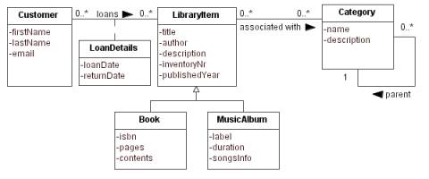
Figure 3 – MagicLibrary
Conceptual Model
The
business concepts model can be elaborated into implementation-specific models
by performing specific transformations and adding details. We will shortly
discuss the strategy for transforming the MagicLibrary conceptual model to
relational model and present the transformed relational model.
4.3. Strategy for Mapping
Concepts to Relational Data
We suggest the following strategy for
transforming business concepts model to relational data model:
- Changing business concepts to tables: this is as simple as copying
classes from conceptual model to relational data model and adding
stereotype <<table>> to each of the classes.
- Adding primary key fields: tables in relational
databases should have primary key fields thus we need to add field with
conventional name id and stereotype <<PK>> to each of
the classes.
- Specifying data types: we need to choose and specify
database-specific data types for table fields.
- Mapping relationships to foreign keys: relationships between the
concepts should be mapped to foreign key constraints between the tables.
Relationships one-to-one and one-to-many are implemented as a foreign key
association between tables with foreign key field stored at the concept
which is more specialized (in case of one-to-one relationship, e.g.
generalization) or which has multiplicity many (in case of
one-to-many relationship). Mapping relationships many-to-many requires
adding table with foreign keys to both of classes corresponding to related
concepts. This is only one of available strategies for mapping objects to
relational tables as suggested in (IBM, 2003a) and (Ambler, 2004).
- Adding application-specific data details: additional constraints
specific to your application are specified, e.g. we will add a constraint
for checking that published year for library item should be more than
1900. This also includes specifying column multiplicities, which for
relational model should be [1] if column is compulsory and [0..1] if
column is optional.
- Adding application-specific data views: if necessary you may also
model views that show temporary data selected from database tables, e.g.
we will create a view, which shows end-user information about active
loans: customer’s first and last name and e-mail address, loaned item’s
title and inventory number, and date when it was loaned.
Regarding the naming conventions, we reuse
conventions for Java source code (Sun, 1999): table naming corresponds to Java
class naming and column names and constraints correspond to Java attribute and
operation naming. For foreign keys we use specific naming starting with fk_
and followed by logical role name of referenced table.
4.3.
Relational Data Model
Applying
the above discussed strategy we have created the relational model, which is
represented by DDL diagram given in Figure 4. Since we intend to use UML model
for generating DDL script executable on Oracle 9i system, we have specified
data types specific to Oracle RDBMS. For mapping many-to-many relationship
between LibraryItem and Category we have created intermediate
table ItemCategories storing pairs of foreign keys to LibraryItem
and Category, and for mapping many-to-many relationship between Customer
and LibraryItem we have created intermediate table Loan, storing
pairs of foreign keys to Customer and LibraryItem and properties
specified in association class LoanDetails – loan date and return date,
which is null until loaned item is returned. We have mapped generalizations to
compositions, since it is a strict one-to-one relationship, where LibraryItem
stores part of Book or MusicAlbum information, which is not
shared.
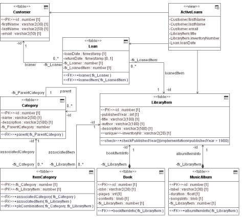
Figure 4
– MagicLibrary Relational Model
Using the above displayed relational model
expressed in UML, we have generated corresponding DDL script***, which is given in the Table 4. This
script can be executed on Oracle 9i system****
for creating corresponding table structure in default database schema. After
executing the DDL statement you may also update your UML model by retrieving
database structure from Oracle 9i system. Note, that after this retrieval
additional database elements that were either added according to the DDL
engineering set properties, such as Generate Not Null Constraint, or
automatically created by database system, such as indices for primary keys and
unique values, will be added to your model. However, with MagicDraw UML you may
always specify what elements you need to show in diagram and what you want to
hide, so that the diagram were clear and important elements were not obscured
by unimportant database-specific details.
Table 4 – DDL script generated
from MagicLibrary relational model
|
CREATE TABLE Customer ( id number NOT NULL PRIMARY KEY, firstName varchar2 (30) NOT NULL, lastName varchar2 (50) NOT NULL, email varchar2 (50) NOT NULL ); CREATE TABLE LibraryItem ( id number NOT NULL PRIMARY KEY, publishedYear int NOT NULL, title varchar2 (100) NOT NULL, author varchar2 (100) NOT NULL, description varchar2 (500) NOT NULL, inventoryNr varchar2 (20) NOT NULL UNIQUE, CONSTRAINT checkPublishedYear CHECK(publishedYear
> 1900) ); CREATE TABLE Category ( id number NOT NULL PRIMARY KEY, name varchar2 (50) NOT NULL, description varchar2 (500) NOT NULL, fk_ParentCategory number, CONSTRAINT parent FOREIGN KEY(fk_ParentCategory)
REFERENCES Category (id) ); CREATE TABLE ItemCategory ( fk_Category number NOT NULL, fk_LibraryItem number NOT NULL, CONSTRAINT associatedCategory FOREIGN
KEY(fk_Category) REFERENCES Category (id), CONSTRAINT associatedItem FOREIGN
KEY(fk_LibraryItem) REFERENCES LibraryItem (id), CONSTRAINT pkCombination PRIMARY KEY(fk_Category,
fk_LibraryItem) ); CREATE TABLE Loan ( loanDate timestamp NOT NULL, returnDate timestamp, fk_Loaner number NOT NULL, fk_LoanedItem number NOT NULL, CONSTRAINT loaner FOREIGN KEY(fk_Loaner) REFERENCES
Customer (id), CONSTRAINT loanedItem FOREIGN KEY(fk_LoanedItem)
REFERENCES LibraryItem (id) ); CREATE TABLE MusicAlbum ( id number NOT NULL PRIMARY KEY, label varchar2 (30) NOT NULL, duration float NOT NULL, songsInfo blob NOT NULL, fk_LibraryItem number NOT NULL, CONSTRAINT albumItemInfo FOREIGN KEY(fk_LibraryItem)
REFERENCES LibraryItem (id) ); CREATE TABLE Book ( id number NOT NULL PRIMARY KEY, isbn varchar2 (20) NOT NULL, pages int NOT NULL, contents blob NOT NULL, fk_LibraryItem number NOT NULL, CONSTRAINT bookItemInfo FOREIGN KEY(fk_LibraryItem)
REFERENCES LibraryItem (id) ); CREATE VIEW ActiveLoans AS SELECT Customer.firstName, Customer.lastName,
Customer.email, LibraryItem.title, LibraryItem.inventoryNr, Loan.loanDate FROM Loan, LibraryItem, Customer WHERE Loan.returnDate IS NULL AND Loan.fk_LoanedItem
= LibraryItem.id AND Loan.fk_Loaner = Customer.id; |
5. Conclusions
In this paper we have discussed the issues of
applying UML for modeling data structures supported in relational databases. We
introduced the benefits of reusing UML for database modeling and gave a short
review of existing approaches to this problem. We have presented the details of
using UML for modeling relational data supported in MagicDraw UML tool:
- UML profile for DDL and mappings of relational data concepts to UML
elements;
- Generating DDL scripts from UML model;
- Reversing UML model from DDL scripts;
- Retrieving UML model from existing databases;
- Supporting multiple database dialects.
A case study of applying this approach for
modeling relational data for a library system was given. A simple but effective
strategy for transforming conceptual model into database-specific UML model was
presented. We have also indicated the future work, which needs to be done to
increase efficiency of modeling relational data with UML.
References
1.
Ambler, S.W., 2003, Agile Database
Techniques: Effective Strategies for the Agile Software Developer, John
Wiley & Sons
2.
Ambler, S.W., 2004, The Fundamentals of
Mapping Objects to Relational Databases; http://www.agiledata.org/essays/mappingObjects.html
3.
Ambler, S.W., 2004a, A UML Profile for Data
Modeling; http://www.agiledata.org/essays/umlDataModelingProfile.html
4.
Elmasri, R., and Navathe, S. B., 2003, Fundamentals
of Database Systems, 4th edition, Addison Wesley.
5.
Fowler, M., 2003, UML Distilled: A Brief
Guide to the Standard Object Modeling Language, 3rd edition, Addison-Wesley
6.
Halpin, T., Bloesch, A., 1999, Data modeling in
UML and ORM: a comparison, in Journal of Database Management, vol.
10(4); http://www.orm.net
7.
IBM, 2003, Entity Relationship Modeling with
UML, http://www3.software.ibm.com/ibmdl/pub/software/rational/web/whitepapers/2003/ermodeling.pdf
8.
IBM, 2003a, Mapping Object to Data Models
with the UML, http://www3.software.ibm.com/ibmdl/pub/software/rational/web/whitepapers/2003/tp185.pdf
9.
Muller, R., 1999, Database Design for
Smarties: Using UML for Data Modeling, Morgan Kaufmann
10. Naiburg, E. J., Maksimchuk, R. A., 2001, UML for Database Design,
Addison-Wesley
11. No Magic, 2004, MagicDraw Code and Database Engineering Version 7.5
User’s Guide; http://www.magicdraw.com
12. OMG, 2003, OMG Unified Modeling Language Specification, Version
1.5; http://www.omg.org/cgi-bin/doc?formal/03-03-01
13. OMG, 2003a, MDA Guide; http://www.omg.org/cgi-bin/doc?mda-guide
14. Sun Microsystems, 1999, Code Conventions for the Java Programming
Language, http://java.sun.com/docs/codeconv/
15. Sun Microsystems, 2003, Java 2 Platform, Standard Edition, v 1.4.2
API Specification; http://java.sun.com/j2se/1.4.2/docs/api/index.html